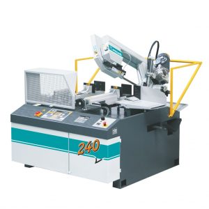
 240x280 A-CNC-R / Automatic band saw machine
 It's no longer on sale
| mm | 0° | 45° | 60° | -45° | -60° |  |
 |
|---|---|---|---|---|---|---|---|
 |
240 | 190 | 120 | x | x | x | x |
 |
150* | 110* | 80* | x | x | x | x |
 |
280x220 | 190x170 | 120x150 | x | x | 230x120 |
 |
 |
 |
 |
 |
|---|---|---|---|---|
| 3x400V | 1,4/2,0 | 35/70 | 2980x27x0,9 | 800 |
| Lmin | Lmax | Bmin | Bmax | Hmin | Hmax | V |
|---|---|---|---|---|---|---|
| 2150 | 2150 | 1750 | 2200 | 1400 | 1900 | 940 |
It is a highly efficient automatic hydraulically controlled band-saw with multiple material feed. The machine is designed for vertical and angular cuts. Angular cuts are fluently adjustable from 0 to +60 grades right in semiautomatic mode. It is suitable for serial production and thank to its robust construction enables to cut wide range of materials including stainless stells and tool steels both profiles and full materials.
Control systém:
The saw is equpped with safety red button for emergency stop, manual regulator of arm and control system SAW-MICRO (8-bit processor which controls each movements and programms).
SAW MICRO: The length and number of pieces are set on the control panel. The machine selects the number of feeds and performs the necessary calculations by itself. The system allows the selection from nine different settings for quick adjustment of lengths or automatic modification of lengths when sawing several dimensions from one bar. There is an automatic and a semiautomatic mode, where all movements are controlled independently.
Regulation of shaft speed (moving to cut) is manual and uses throttle valve placed beside control panel. Automatic (safety) regulation of shift speed PEGAS BRP. Principle: Machine will stop after exceeding set loading (defined in ampers).
The controlling panel is equipped with a safety button, which stops the saw, and another two buttons for turning it on. Buttons for machine movements handling are parts of high quality control keyboard.
Construction:
The machine is constructionaly designed in that way, so that it corresponds to standard exertions in productive conditions. That is why all carrying parts are made as cast-iron castings (solidity, absorbtion of vibrations and stops). Parts of arm, vice and turn table is cust iron.
The arm of the machine is made of cust iron and it is designed to ensure the power and the precision of the cut. Arm is 25 grades sloped, it increases the lifetime of blade.
Arm is placed in adjustable bearings.
Drive pulley and tighten pulley are both metal castings.
Working position of the arm is controlled by the cam and microswitches of the upper and down position of the arm. The arm goes back to the set position automatically after reaching the down limit position.
The vice is welded. The jaw is made from cast iron. Jaw ensures the safe clamping of the material.
The hydraulically operating vice with short travel is placed in an adjustable dovetail groove.
Moving jaw of the vice is manual with a wheel and trapeze thread.
Very massive feeder moves using hydraulic cylinder and two sparpened bars and teflon cases.
There is a floating seating of the feeding vice in the feeder, it means that the feeding vice moves in perpendicular sense regarding the feeding sense. The stationary jaw of the feeding vice copies the possible roughness of feeded material and the worning out of mechanical parts of the feeder is eliminated.
The feeder moves the material to be cut to the main vice according to the set lenght that was adjusted by the operator in the controlling panel. The position of the feeder is indicated by electromagnetic sensor and measuring magnetic tape. For a perfect placing of a feeder , feeder moves to end positions by a slow velocity.
The clamping of material in the feeding vice in indicated by the mikroswich.
The feeder clamping vice is made from cast iron. Jaws ensure safe clamping of the material.
Hydraulic, short stroke cylinder of the feeder is placed in adjustabled dovetail groof. Jaw moving is using hanlde and adjustable screw.
Turn table is cust iron.
Manuall turning of the table for angle cuts, angle fixation using quick clamping lever.
General angles are adjusted by the nonius.
Basic equipment of machine:
The blade leading in guides with hardmetal plates and leading bearings and along cast iron pulleys.
There is a guide situated on the firm beam on the drive side. On the tightening side there is the guide situated on the moving beam.
The guide beams of moving band guide is adjustable in whole working range. Manual adjustment and fixing of the guide beams.
Guide holder moves in adjustabled dovetail groof.
The saw-band is equipped with a guard, which protects the operator from millings and cutting emulsion.
Mechanic tightening of the blade.
Automatic indication of blade tension.
A passive driven cleaning brush for perfect cleaning and function of blade.
Drive of machine is solved by worm gear box with maintenanceless oil filling. Three-phases electromotor with double winding, with a frequency converter for a fluent regulation of the blade speed from 20 to 100 m/min. Sturdy flange with shaft. Termoprotection of engine.
The cooling system distributes cutting emulsion to the band guides.
Massive base with a tank for chips. Base is designed for manipulation manipulation with machine by pallet truck and also by any hight lift truck.
Indication of blade tightening and opening of the cover.
Controlling 24 V.
Machine is equipped with hydraulic system which controles all functions of that maschine. It pushes the arm to cut, pulls up the arm, opens and closes vices, moving of feeder.
Basic equipment of machine:
Slide of cut pieces.
Band saw blade.
Set of spanners for common service.
Manual instructions in eletronic form (CD).
Operating cycle:
The machine automatically grips the material in the main vice and the feeder moves into a position determined by the processor (i.e. the required length of the cut and a constant added length); the feeder-vice’s jaw stays open. The arm moves into the cut; after cutting the material, it moves into the upper position. The feeder moves by the constant added length (exactly to a position determined by the processor) and the feeder jaw grips the material. The vice is released; the feeder moves the material into the zero position (by the required length). The main vice grips, the feeder-vice is released and the entire cycle is repeated.The operator only removes the sawn material.
| Code | Description | Type |
|---|
Tech. data NO241 are valid on 1.1.2024. Producer has the right to make changes of technical data.
Values contained on this page are only for information purposes. This information is not an offer and is not a public promise. This indicative offer does not give right to close a contract. The only guiding document for the contract is a valid price list.