Highly-efficient double-column band saw machines ->
CALIBER ->
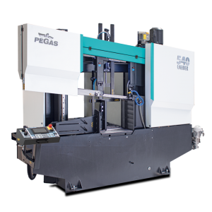
540 CALIBER A-CNC-2M
 540 CALIBER A-CNC-2M / CALIBER

| mm | 0° | 45° | 60° | -45° | -60° |  |
 |
|---|---|---|---|---|---|---|---|
 |
550 | x | x | x | x | ||
 |
550x500 | x | x | x | x | 550x460 |
 |
 |
 |
 |
 |
|---|---|---|---|---|
| 3 x 400V | 5,5 | 15-150 | 6200 x 41 x 1,3 | 5100 |
| Lmin | Lmax | Bmin | Bmax | Hmin | Hmax | V |
|---|---|---|---|---|---|---|
| 3350 | 4116 | 3500 | 3500 | 2425 | 2522 | 800 |
- Highly productive, automatic dual column band saw with multiple material feeding
- The saw is designed for cutting material in straight cuts
- The saw has the concept FVC = feeder – cut - main vice. The FVC concept enables cutting of single bars and bundles in an automatic cycle with short residue.
- The saw is used in serial production in industrial plants and it can cut a wide range of material grades including stainless and tool steels due its robust design.
- The saw is designed for cutting straight bars of steel material.
Control system:
- The machine is equipped with programmable PLC MITSUBISHI FX5_U64. The saw blade drive and feeder movement are completely controlled by MITSUBISHI technology.
- The colour touch screen allows easy communication with the machine operator. It shows working states such as blade speed, cutting feed and the status of individual working movements.
- Display size 7' (92x153mm)
- The saw allows you to work with two modes:
- SEMI-AUTOMATIC (MANUAL) MODE: The saw immediately cuts the material in semi-automatic mode. The operator uses the saw's feeder to manipulate the material to be cut and to accurately move the material into the cut zone. The movement of the feeder is realized by manual buttons or by the GTO function. After starting the GTO function, the operator enters the position of the feeder and pressing the START GTO button moves the feeder to the entered position.
- AUTOMATIC MODE: The feeder feeds the cut blank based on the set program. The operator sets the cutting program and the saw then executes these programs. The operator can store up to 100 programs. One program includes complete cutting settings: blade speed, cutting bar height setting, bar length setting and number of cuts. The length and number can be set in 20 lines. The saw automatically feeds the different lengths entered.
- Control of the cutting feed is ensured by a hydraulic throttle valve with RTR function.
- The control panel is located on the console in a safe position. The control panel includes a digital display of the saw control system and a high quality foil keypad. The keypad is used to control the basic movements of the saw (movement of the arm, vices and feeder) and to start the saw's working cycle. The control panel is also equipped with a safety button to stop the saw.
- Safety module with self-diagnosis.
- 24V control
Construction:
- The band saw has a robust design to withstand extreme stresses in production conditions. All machine components are designed and optimized to minimize vibrations and allow maximum cutting performance of the machine.
- Saw blade speed range 15 - 150m/min.
- The saw arm with the columns close to the clamping vice and the saw blade close to the columns minimize vibrations and allow maximum cutting performance of the machine.
- The arm is a robust weldment and is designed to ensure the necessary rigidity and cutting accuracy
- The arm moves on two columns using a four-row linear guide with a high load capacity.
- Arm movement by hydraulic cylinder
- The saw blade is guided on robust cast iron pulleys.
- WRS - Reinforcement of pulley mounting - drive pulley mounted directly on the output shaft of the gearbox. The pulley is supported on both sides by a bearing seat =minimizing the load on the shaft seat. The tension pulley is held/tensioned by two hydraulic cylinders at both ends of the centre pin =significant reduction of stress and extension of the life of the bearing. The tension pulley mounting is with zero play=conical bearings secured by KM nut.
- The saw uses a sensor and magnetic tape to evaluate the position of the arm above the material. The upper and lower working position of the arm is set by entering a value into the saw control system. The lower end position can also be determined by a limit switch.
- The main vise is a robust steel weldment.
- Movement of the long stroke jaws of the main vise along two rails of the linear guide, by means of a hydraulic cylinder. The long stroke jaw ensures full stroke = clamping even very small bars. The second jaw is fixed. Accessory at extra cost is a short stroke jaw = non-contact feeding of curved material. The short stroke jaw is mounted on a linear guide. The stroke of the short stroke roller is 15 mm
- Control valve for vise pressure adjustment, pressure indication on pressure gauge
- Feeder movement by linear guide, ball screw, preloaded nut, toothed belt transmission and asynchronous motor.
- Precise positioning of the feeder is solved automatically by the Mitsubishi frequency inverter. An incremental rotary encoder to indicate the position of the feeder. When stopped, the motor is fixed by a brake.
- Material indication in the feeder: an optical sensor indicates that there is material in the feeder. If there is no material in the feeder, the saw finishes feeding the rest of the bar and waits for the next bar to be inserted.
- A roller conveyor supporting the fed material along its entire length passes through the saw.
- The feeding vise is a robust steel weldment. The jaws ensure secure clamping of the material.
- Movement of the jaws of the feeding vise along two rails of the linear guideway, using hydraulic cylinders. One jaw is long stroke hydraulic cylinder. The other jaw is short stroke. Short-stroke jaw = non-contact reverse motion of the feeder. Advantage when feeding crooked material.
- GTO function (go to position).
- The saw allows two basic feeding modes:
- o NORMAL: the feeder moves between the zero position and the position of the specified feed length.
- o INCREMENTAL: the feeder moves to the limit position, clamps the bar and feeds it sequentially into the cut.
- Feeder movement modes:
- o CONTINUAL: optimal for cutting longer bars
- o STEP BY STEP: requires cooperation with the machine operator when taking short pieces. Each step of the program must be confirmed by the machine operator
- CMU mode: opening of the cutting zone on the feeder side for non-contact movement of the saw blade to the upper position. It is used especially when using carbide blades
- Saw blade drive via bevel gearbox and three-phase electric motor with variable blade speed control by frequency inverter
- External fan cooling of the saw blade drive.
- Thermal protection of the electric motor.
- The blade is guided in guides with carbide plates, bearings, then on cast iron pulleys and in the upper part (reverse) the blade is supported by vibration dampers.
- The inclination of the saw blade against the plane of the vise is 7 degrees. This ensures higher performance when cutting profiles and bundles and at the same time increases the life of the saw blade.
- The saw has a guide on the drive side mounted on a fixed beam. On the tensioning side, the guide is mounted on a sliding beam.
- Blade guide beam adjustable over the entire working range. The movement of the guide is linked to the movement of the vice clamp. It is therefore not necessary to manually adjust its position.
- The guide beam moves by means of a linear guide (2 rails, 3 trolleys) with high load capacity.
- A new way of mounting the guides - a solution with a regulated spacer.
- BGT-S - mechanical pressure of the saw blade in the guides by means of disc springs
- The space between the saw blade guide and the pulley is provided with a cover to protect the operator from the moving saw blade. The covers also protect the surrounding area from falling chips and cooling emulsion.
- The saw is equipped as standard with hydraulic saw blade tensioning - allowing ideal cutting conditions to be maintained at all times. The tensioning force is provided by 2 hydraulic cylinders.
- Automatic Indication of correct saw blade tension by means of a pressure sensor.
- The electric motor-driven brush ensures perfect cleaning of the saw blade.
- Robust base with chip tray and chip extractor. The base is adapted for handling the saw with a crane.
- Cooling system for cutting emulsion, fed into the blade guides and directly into the cutting channel using the flexible LocLine system.
- Microswitches for opening pulley covers.
- Hydraulic unit is located outside the base - better cooling and access. The hydraulic unit controls the saw functions: arm movement, opening and closing the main and feed vise and tensioning the saw blade. The hydraulic oil pump is located outside the oil tank.
- A complete bodywork that covers the arm and feeder movements. The bodywork minimizes the risk of injury and contamination of the saw surroundings by chips and cutting emulsion.
- The chip conveyor. Type. Drive: worm gearbox + electric motor. Thermal protection against motor overheating.
- Chip rinsing pistol
- LED strip for work area lighting.
Basic equipment of the machine:
- Saw blade
- Tool set for routine machine maintenance.
- Operating instructions in electronic form on CD
Do you like this?
Contact us
or send inquiry!
or send inquiry!