Double-column band saw machines for angular cutting ->
Horizont ->
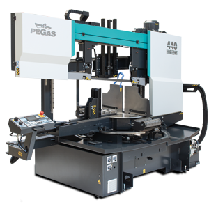
440 HORIZONT SHI
 440 HORIZONT SHI / Horizont

| mm | 0° | 45° | 60° | -45° | -60° |  |
 |
|---|---|---|---|---|---|---|---|
 |
440 | 430 | 290 | 430 | 290 | 610x350 | |
 |
610x385 | 430x385 | 290x385 | 430x385 | 290x385 | 610x350 |
 |
 |
 |
 |
 |
|---|---|---|---|---|
| 3x400V | 4,0 | 15-150 | 6060x34x1,1 | 2080 |
| Lmin | Lmax | Bmin | Bmax | Hmin | Hmax | V |
|---|---|---|---|---|---|---|
| 4341 | 1756 | 1756 | 2168 | 2225 | 810 |
- Highly productive, semi-automatic dual column band saw machine.
- The saw is designed for cutting material in both straight and angular cuts, angular cuts adjustable 150° left, 90° perpendicular, 30° right (+/- 60 degrees).
- The saw is designed for cutting bars of solid material and profiles.
- Saw is used in series production in industrial plants. The saw is designed for cutting straight bars of steel material.
Control system:
- The machine is equipped with programmable PLC MITSUBISHI FX5_U64. The saw blade drive and arm movement are completely controlled by MITSUBISHI technology.
- The colour touch screen allows easy communication with the machine operator. It shows working states such as blade speed, cutting feed and the status of individual working movements.
- Display size 4.3' (56x96mm)
- Control of the cutting feed is ensured by a hydraulic throttle valve with RTR function.
- RTO (rotate to) function for automatic rotation to set angle.
- The control panel is located on the console in a safe position. The control panel includes a digital display of the saw control system and a high quality foil keypad. The keypad is used to control the basic movements of the saw (movement of the arm, vice and turntable) and to start the saw's working cycle. The control panel is also equipped with a safety button to stop the saw.
- Safety module with self-diagnosis.
- 24V control
Construction:
- The saw is designed to fully support the efficient use of carbide saw blades. The band saw has a robust design to withstand extreme stresses in production conditions. All machine components are designed and optimized to minimize vibrations and allow maximum cutting performance of the machine.
- The saw arm with the columns close to the clamping vice and the saw blade close to the columns minimize vibrations and allow maximum cutting performance of the machine.
- Saw blade speed range 15 - 150m/min.
- The arm is a robust weldment and is designed to ensure the necessary rigidity and cutting accuracy
- The saw blade is driven by a bevel gearbox, asynchronous motor and frequency inverter.
- External fan cooling of the saw blade drive.
- The arm moves on two columns using a four-row linear guide with a high load capacity.
- Arm movement by hydraulic cylinder
- The saw blade is guided on robust cast iron pulleys.
- WRS - Reinforcement of pulley mounting - drive pulley mounted directly on the output shaft of the gearbox. The pulley is supported on both sides by a bearing seat =minimizing the load on the shaft seat. The tension pulley is held/tensioned by two hydraulic cylinders at both ends of the centre pin =significant reduction of stress and extension of the life of the bearing. The tension pulley mounting is with zero play=conical bearings secured by KM nut.
- The saw uses a sensor and magnetic tape to evaluate the position of the arm above the material. The upper and lower working position of the arm is set by entering a value into the saw control system. The lower end position can also be determined by a limit switch.
- Main vise with split clamp for fixing the workpiece before and after the cut (straight cuts). The clamps ensure secure clamping of the material.
- Movement of the clamp of the main vise in the rigid steel guide by means of a long-stroke hydraulic cylinder.
- Two robust vise support clamps
- Control valve for vise pressure adjustment, pressure indication on pressure gauge
- The turntable is a robust weldment. Rotary table for angle cuts with machined base guide surface. The rotary table adds a large space for supporting the material and clamping it precisely. Rotation of the angle cutting table by means of a hydraulic cylinder and a linear guide, driven by gear and rack.
- Angle adjustment control:
o Rotation via the button to the desired angle (fast-shift / slow-shift)
o Using the RTO (rotate to position) function with automatic adjustment of the desired arm rotation position
- Hydraulic position locking "lock"
- Turntable angle displayed on the Mitsubishi control panel display. Indication of set angle by incremental sensor and magnetic tape.
- Optimisation of the chip movement to the chip box or chip ejector, which is offered as an accessory
- Belt guidance in guides with plates and guide bearings and on cast iron pulleys. Adjustable guides with zero cutting clearance, preloaded by plate springs.
- Robust flange with drive shaft mounting via roller bearing.
- The inclination of the saw blade against the plane of the vise is 7 degrees. This ensures higher performance when cutting profiles and bundles and at the same time increases the life of the saw blade.
- The saw has a guide on the drive side mounted on a fixed beam. On the tensioning side, the guide is mounted on a sliding beam.
- Blade guide beam adjustable over the entire working range. The movement of the guide is linked to the movement of the vice clamp. It is therefore not necessary to manually adjust its position.
- The guide beam moves by means of a linear guide (2 rails, 3 trolleys) with high load capacity.
- A new way of mounting the guides - a solution with a regulated spacer.
- The space between the saw blade guide and the pulley is provided with a cover to protect the operator from the moving saw blade. The covers also protect the surrounding area from falling chips and cooling emulsion.
- The saw is equipped as standard with hydraulic saw blade tensioning - allowing ideal cutting conditions to be maintained at all times. The tensioning force is provided by 2 hydraulic cylinders.
- Automatic Indication of correct saw blade tension by means of a pressure sensor. Cleaning brush passively driven by a pulley in the basic version, electric motor as optional
- Cooling system for cutting emulsion, fed into the blade guides and directly into the cutting channel using the flexible LocLine system.
- Robust base with chip tray. The base is designed for handling the saw with a crane
- Microswitches for opening pulley covers.
- Hydraulic unit located outside the base - better cooling and access. The hydraulic unit controls the functions of the saw: movement of the arm, opening and closing the main vice, rotating the turntable for angle cuts and fixing the turntable in the set rotation. The hydraulic oil pump is located outside the oil tank.
- Two rollers for supporting the cut material. Retractable via linear guide. Positioning on the output side
- Cover bodywork that covers the movements of the rear of the arm. The body minimises the risk of injury and contamination of the saw's surroundings with chips and cutting emulsion.
- Chip rinsing pistol
- LED strip for work area lighting.
Basic equipment of the machine:
- Saw blade
- Tool set for routine machine maintenance.
- Operating instructions in electronic form on CD.
Do you like this?
Contact us
or send inquiry!
or send inquiry!