Double-column band saw machines for angular cutting ->
Horizont ->
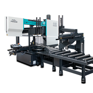
440 HORIZONT A-CNC
 440 HORIZONT A-CNC / Horizont

| mm | 0° | 45° | 60° | -45° | -60° |  |
 |
|---|---|---|---|---|---|---|---|
 |
440 | 430 | 290 | 430 | 290 | 610x350 | |
 |
610x385 | 430x385 | 290x385 | 430x385 | 290x385 | 610x350 |
 |
 |
 |
 |
 |
|---|---|---|---|---|
| 3x400V | 4,0 | 15-150 | 6060 x 34 x 1,1 | 3280 |
| Lmin | Lmax | Bmin | Bmax | Hmin | Hmax | V |
|---|---|---|---|---|---|---|
| 3311 | 4160 | 6010 | 6010 | 2168 | 2225 | 810 |
- Highly productive, automatic dual column band saw with multiple material feeding
- The saw is designed for cutting material in both straight and angular cuts, angular cuts adjustable 150°left, 90°perpendicular, 30°right (+/- 60 degrees).
- The saw is designed for cutting bars of solid material and profiles.
- Saw is used in series production in industrial plants. The saw is designed for cutting straight bars of steel material.
Control system:
- The machine is equipped with programmable PLC MITSUBISHI FX5_U64. The saw blade drive and arm movement are completely controlled by MITSUBISHI technology.
- The colour touch screen allows easy communication with the machine operator. It shows working states such as blade speed, cutting feed and the status of individual working movements.
- Display size 7' (92x153mm)
- The saw allows you to work with two modes:
- SEMI-AUTOMATIC (MANUAL) MODE: The saw immediately cuts the material in semi-automatic mode. The operator uses the saw's feeder to manipulate the material to be cut and to accurately move the material into the cut zone. The movement of the feeder is realized by manual buttons or by the GTO function. After starting the GTO function, the operator enters the position of the feeder and pressing the START GTO button moves the feeder to the entered position.
- AUTOMATIC MODE: The feeder feeds the cut blank based on the set program. The operator sets the cutting program and the saw then executes these programs. The operator can store up to 100 programs. One program includes complete cutting settings: blade speed, cutting feed value, cutting bar height setting, bar length setting and number of cuts. The length and number can be set in 20 lines. The saw automatically feeds the different lengths entered.
- Regulation of cutting feed is realized by controlled systém by the servo-motor and throttle valve hydraulics. Then is reached very precise cutting feed. Operator will input into program requiered cutting feed (mm/min) and bandsaw this cutting feed precisely set.
- Two basic regimes of automatic system regulation (ASR): ARP a RZP-2.
- RZP-2: cutting zones regulation. System enables to set of optimal shift speed (movement to cut) and blade speed in 5 different zones depending on blade position.
- ARP = System of the automatic regulation of the cutting feed rate depending on the cutting resistance of the material or blunting the blade.
- System offers two basic modes of ARP: BIMETAL and CARBIDE.
- BIMETAL mode is suitable for optimalization of the cutting feed when cutting profiles by bimetal blades. The cutting feed is higher if the blade cuts sides of the profile. As the blade reaches the full material, the system reduces the cutting feed automatically so that teeth gap of the blade would not be filled.
- CARBIDE mode is suitable for cutting of full bars. If the blade is old (blunt), loaded is the cutting feed reduced Reaction time is slower than in mode BIMETAL.
- The control panel is located on the console in a safe position. The control panel includes a digital display of the saw control system and a high quality foil keypad. The keypad is used to control the basic movements of the saw (movement of the arm, vices, turntable and feeder) and to start the saw's working cycle. The control panel is also equipped with a safety button to stop the saw.
- Safety module with self-diagnosis.
- 24V control
Construction:
- The band saw has a robust design to withstand extreme stresses in production conditions. All machine components are designed and optimized to minimize vibrations and allow maximum cutting performance of the machine.
- The saw arm with the columns close to the clamping vice and the saw blade close to the columns minimize vibrations and allow maximum cutting performance of the machine.
- Saw blade speed range 15 - 150m/min.
- The arm is a robust weldment and is designed to ensure the necessary rigidity and cutting accuracy
- Saw blade drive via bevel gearbox and three-phase electric motor with variable blade speed control by frequency inverter
- External fan cooling of the saw blade drive.
- The arm moves on two columns using a four-row linear guide with a high load capacity.
- Arm movement by hydraulic cylinder
- The saw blade is guided on robust cast iron pulleys.
- WRS - Reinforcement of pulley mounting - drive pulley mounted directly on the output shaft of the gearbox. The pulley is supported on both sides by a bearing seat =minimizing the load on the shaft seat. The tension pulley is held/tensioned by two hydraulic cylinders at both ends of the centre pin =significant reduction of stress and extension of the life of the bearing. The tension pulley mounting is with zero play=conical bearings secured by KM nut.
- The saw uses a sensor and magnetic tape to evaluate the position of the arm above the material. The upper and lower working position of the arm is set by entering a value into the saw control system. The lower end position can also be determined by a limit switch.
- Main vise with split clamp for fixing the workpiece before and after the cut (straight cuts). The clamps ensure secure clamping of the material.
- Movement of the clamp of the main vise in the rigid steel guide by means of a long-stroke hydraulic cylinder.
- Two robust vise support clamps
- Control valve for vise pressure adjustment, pressure indication on pressure gauge
- The very rigid feeder moves by 2 linear guide rails.
- Feed step 2000 mm, multiple feed (max. length 9999 mm)
- Feeder movement by linear guide, ball screw, toothed belt transmission and servo drive.
- Precise positioning of the feeder is solved automatically by the Mitsubishi frequency inverter. An incremental rotary encoder to indicate the position of the feeder is included in the actuator. When stopped, the motor is fixed by the brake.
- Material indication in the feeder: an optical sensor indicates that there is material in the feeder. If there is no material in the feeder, the saw finishes feeding the rest of the bar and waits for the next bar to be inserted.
- A roller conveyor passes through the feeder supporting the material along the entire length of the feed.
- The feeding vise is a robust steel weldment. The jaws ensure secure clamping of the material.
- Movement of the jaws of the feeding vise along two rails of the linear guideway, using hydraulic cylinders. One jaw is long stroke hydraulic cylinder. The other jaw is short stroke. Short-stroke jaw = non-contact reverse motion of the feeder. Advantage when feeding crooked material.
- GTO function (go to position).
- The saw allows two basic feeding modes:
o NORMAL: the feeder moves between the zero position and the position of the specified feed length.
o INCREMENTAL: the feeder moves to the limit position, clamps the bar and feeds it sequentially into the cut.
- Feeder movement modes:
o CONTINUAL: optimal for cutting longer bars
o STEP BY STEP: requires cooperation with the machine operator when taking short pieces. Each step of the program must be confirmed by the machine operator
- CMU mode: opening of the cutting zone on the feeder side for non-contact movement of the saw blade to the upper position. It is used especially when using carbide blades.
- The turntable is a robust weldment. Rotary table for angle cuts with machined base guide surface. The rotary table adds a large space for supporting the material and clamping it precisely. Rotation of the angle cutting table by means of a hydraulic cylinder and a linear guide, driven by gear and rack.
- Angle adjustment control:
o Rotation via the button to the desired angle (fast-shift / slow-shift)
o Using the RTO (rotate to position) function with automatic adjustment of the desired arm rotation position
- Automatic rotation after activation of the cutting program
- Hydraulic position "lock"
- Turntable angle displayed on the Mitsubishi control panel display. Indication of set angle by incremental sensor and magnetic tape.
- Optimisation of the chip movement to the chip box or chip conveyor, which is offered as an accessory
- Blade guidance in guides with hardmetal plates, bearings and on cast iron pulleys. Adjustable guides with zero cutting clearance.
- Robust flange with drive shaft mounting via roller bearing.
- The inclination of the saw blade against the plane of the vise is 7 degrees. This ensures higher performance when cutting profiles and bundles and at the same time increases the life of the saw blade.
- The saw has a guide on the drive side mounted on a fixed beam. On the tensioning side, the guide is mounted on a sliding beam.
- Blade guide beam adjustable over the entire working range. The movement of the guide is linked to the movement of the vice clamp. It is therefore not necessary to manually adjust its position.
- The guide beam moves by means of a linear guide (2 rails, 3 trolleys) with high load capacity.
- A new way of mounting the guides - a solution with a regulated spacer.
- The space between the saw blade guide and the pulley is provided with a cover to protect the operator from the moving saw blade. The covers also protect the surrounding area from falling chips and cooling emulsion.
- The saw is equipped as standard with hydraulic saw blade tensioning - allowing ideal cutting conditions to be maintained at all times. The tensioning force is provided by 2 hydraulic cylinders.
- Automatic Indication of correct saw blade tension by means of a pressure sensor.
- Cleaning brush passively driven by a pulley in the basic version, electric motor as optional.
- Cooling system for cutting emulsion, fed into the blade guides and directly into the cutting channel using the flexible LocLine system.
- Robust base with chip tray. The base is designed for handling the saw with a crane.
- Microswitches for opening pulley covers.
- Hydraulic unit located outside the base - better cooling and access. The hydraulic unit controls the functions of the saw: movement of the arm, opening and closing the main vice, rotating the turntable for angle cuts and fixing the turntable in the set rotation. The hydraulic oil pump is located outside the oil tank.
- Two rollers for supporting the cut material. Retractable via linear guide. Positioning on the output side.
- Cover bodywork that covers the movements of the rear of the arm. The body minimises the risk of injury and contamination of the saw's surroundings with chips and cutting emulsion.
- A safety optical barrier ensures operator protection throughout the entire range of movement of the turntable, arm and feeder. Optical line along the entire length of the saw at the operator's position.
- Chip rinsing pistol
- LED strip for work area lighting.
Basic equipment of the machine:
- Saw blade
- Tool set for routine machine maintenance.
- Operating instructions in electronic form on CD.
Do you like this?
Contact us
or send inquiry!
or send inquiry!