 510x510 HERKULES X-CNC / Herkules
 It's no longer on sale
| mm | 0° | 45° | 60° | -45° | -60° |  |
 |
|---|---|---|---|---|---|---|---|
 |
510 | x | x | x | x | x | x |
 |
510 | x | x | x | x | x | x |
 |
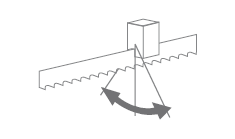
510x530 | x | x | x | x | 510x460 | 510x510 |
 |
 |
 |
 |
 |
|---|---|---|---|---|
| 3x400V | 7,5 | 15-80 | 6060x54x1,6 | 6380 |
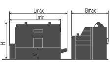
| Lmin | Lmax | Bmin | Bmax | Hmin | Hmax | V |
|---|---|---|---|---|---|---|
| 3360 | 3720 | 2400 | 2400 | 2100 | 2500 | 810 |
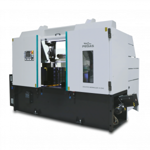
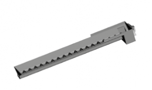
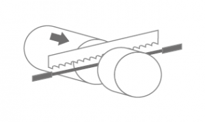
It is a highly efficient automatic hydraulically controlled band-saw with multiple material feed.
Our offer suitable for cutting of the most problematic materials. This machine has a very massive construction and the arm is 25 deg. sloped. These characteristics together with the planet drive and with the blade of 54 mm high ensure the maximum possible efficiency.
The machine is designed for vertical cuts.
It is suitable for serial production in industrial premises. Thanks to its robust construction enables to cut wide range of materials including stainless and tool steels, nonferrous metals both profiles and full materials.
Control systém:
- Machine is equiped with programmable PLC SiEMENS SIMATIC S7-1200. Drive of band blade, movement of arm and movement of feeder are completely controlled and drive by SIEMENS technology.
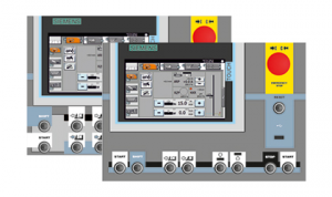
- The coloured touch screen HMI SIEMENS TP 700 COMFORT enables easy communication with an operator. It shows working conditions (blade speed, moving to the cut, cutting parameters etc.)
- The machine enables to work with two modes:
- SEMIAUTOMATIC CYCLE: The machine cuts the material immediatelly in a semiautomatic mode. The operator uses the feeder of the machine for the manipulation with the material and for the exact feed of the material into the cutting zone. The movement of the feeder is realized by manual buttons or by GTO function. After starting GTO function the operator sets the position of the feeder, presses START GTO button and feeder goes to the set position.
- AUTOMATIC CYCLE: the feeder feeds the material according to the set programm. The operator sets the cutting programm, machine realizes these programms, it is possible to make thousand different programms.The part of one programm is a complete setting of the cut: blade speed, feed speed, setting of an automatic regulation, setting of the hight of the bar to be cut, setting of the lenght of the bar, angles values and number of pieces. The lenght and number of pieces it is possible to set in 20 lines, the machine feeds differently set lenghts automatically.
- Regulation of cutting feed is realized by controlled system by the servo-motor and throttle valve of hydraulic. Then is reached very precise cutting feed. Operator will input into program requiered cutting feed (mm/min) and bandsaw this cutting feed precisely set.
- Two basic regimes of automatic system regulation (ASR): ARP a RZP.
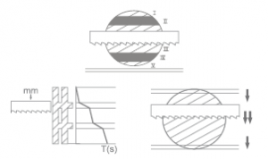
- RZP = Zone regulation. System enable to cut material in 5 zones, because of setting optional cutting feed and blade speed according on blade position. Operator can choose from 2 strategy settings: DEFENSIVE setting is approppriate for cutting very hard materials with use of carbide band blade. Cutting feed is in beginning and in the end reduced. OFENSIVE settings supports executive cutting logs. Cutting feed and band speed are in the beginning and in the end of cut increased. It´s about similar principle as ARP mode. Advantage is regulation of blade speed.
- ARP = System of the automatic regulation of the cutting feed rate depending on the cutting resistance of the material or blunting the blade. Systém offers two basic modes of ARP: BIMETAL and CARBIDE.
- BIMETAL mode is suitable for optimalization of the cutting feed when cutting profiles by bimetal blades. The cutting feed is higher if the blade cuts sides of the profile. As the blade reaches the full material, the system reduces the cutting feed automatically so that teeth gap of the blade would not be filled.
- CARBIDE mode is suitable for cutting of full bars. If the blade is old (blunt), loaded is the cutting feed reduced Reaction time is slower than in mode BIMETAL.
- The control panel is placed in the tightening pulley cover. The control panel is equiped with mechanical buttons and digital display of the machine control system. Mechanical buttons controls basic saw movements (arm, vice, feeder) and cutting cycle start. The safety button is present on the panel aswell. All buttons are highly resistant in anti-vandal version.
- Safety module with autodiagnostics.
Construction:
- The machine is constructionaly designed in that way, so that it corresponds to extreme exertions in productive conditions. Massive construction enables using of carbid blades comfortably.
- The arm of machine with columns situated as near the clamping vice as possible minimizes vibrations and enables max. cutting performance.
- The arm of the machine is robust, heavy weldment and it is designed so that a toughtness and a precision of cut was ensured.
- The arm moves along two columns using a four row linear leading with a high loading capacity. Arm movement using two hydraulic cylinders.
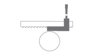
- The robust steel pulleys sloped of 25 degrees regarding the level of the cut. Thanks to sloped arm the twist of the blade is eliminated and these is possibility to bring the blade closer to the minimal distance from the linear leading on columns. This arrangement eliminates vibrations and enables the max. cutting performance of the machine.
- The arm uses incremental sensor for evaluation of current position above material. Upper working position of the arm is possible to set in control system.
- Down working position is set with adjustable mechanical stop and microswitch. Down working position of the arm is also possible to set in the saw control system. After reaching bottom working position the arm stops in the position set in the system.
- Vice is robust steel weldments.
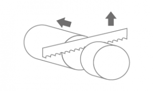
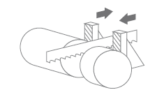
- Main vice with divided jaw that clamps the material in front of as well as behind the cut. The jaws allow a safe grip.The optimalization of the chip movement through the fixed jaw directly to the chip extractor.
- Jaws of the main vice move on two rails of linear leading using hydraulic cylinder. One jaw is longstroke (the movement by longstroke hydraulic cylinder), one is fixed.
- Regulation valves for setting a vice pressure in hydraulic system.
- Very rigid feeder with the feeding step 680 mm moves on four rails of the linear leading by hydraulic cylinders.
- There are two speeds of the feeder (micro feed when approaching the position). Periodic mode (feeder moves between zero position and the position of the set lenght of feed) or consecutive mode (feeder moves to the limit position, clamps the material and feed it to the cut consecutively.
- Incrementally straight sensor for indication of the position of the feeder and GTO (go to position) function. Feeder can have multiple feeding possibility.
- Indication of material in the feeder: optic sensor - it notices that there is a material in the feeder. If there is no material in the feeder, the signal reflects on the glass that is situated on movable jaw and it goes back to the sensor. The machine stops feeding and waits for another bar.
- There is a roller conveyer which supports material in whole feeded lenght.
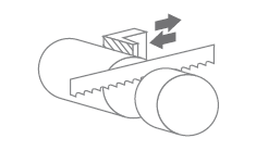
- The feeder clamping vice is a robust steel weldment. Jaws ensure safe clamping of the material.
- Jaws of the feeding vice move along two-rails linears using hydric cylinder. One jaw is long stroke ( the movement by longstroke hydraulic cylinder). Second jaw is short stroke (utilization during bar feeding: not jaw wearing out, not slipping of material). Short stroke jaw is suitable for feeding of deformed material.
- Cutting zone is opened from side of the feeder device automatically, extends the blade lifetime when arm is moving to top position.
Basic equipment of machine:
- The blade leading in guides with hardmetal plates and leading bearings and along cast iron pulleys.
- There is a guide situated on the firm beam on the drive side. On the tightening side there is the guide situated on the moving beam.
- The guide beams of the blade are adjustable in the whole working range. A giude moving is connected with a vice-jaw movement so that to achieve the minimum distance of the guide and material. That is why it is not neccessary to set the position manually.
- The guide beam of the blade is placed in linear rails (2 linear rails and 4 bearings) with high bearing capacity.
- The saw-band is equipped with a guard, which protects the operator from millings and cutting emulsion.
- Hydraulic tightening of band.
- Automatic indication of blade tension.
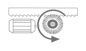
- A cleaning brush is driven by an electroengine and ensures perfect cleaning of a blade.
- There is a planet gear box drive and a three-phase electroengine, a fluent regulation of a blade speed by a frequency converter for a fluent change of blade speed.
- The cooling system for emulsion, leaded to the guides of the blade and by LocLine system directly to the cut groove.
- Massive base with a tank for chips and with chip extractors. Base is designed for manipulation manipulation with machine by crane.
- Indication of blade tightening and opening of the cover.
- Controlling 24 V.
- Machine is equipped with hydraulic system which controles all functions of that maschine. It pushes the arm to cut, pulls up the arm, opens and closes vices, moving of feeder.
Basic equipment of machine:
- Chip extractor
- Lighting of workink space.
- Band saw blade.
- Set of spanners for common service.
- Manual instructions in eletronic form (CD).
Operating cycle:
After starting the machine, vices clamp after starting the machine, the machine makes the cut by a set speed, the cutting zone in the down position of the arm is released - the longstroke jaw of the firm vice open, the feeder moves the material to the firm vice, the arm lifts up to the set upper position. The material is moved by the feeder – periodic regime (feeder moves between zero position and the position of the set lenght of feed) or consecutive regime (feeder moves to the limit position and clamps the material and feed it to the cut consecutively). The main vice clamps the material, the vice of the feeder is still closed and the whole procedure repeats. The operator only loads the material and removes the cut material. It is possible to regulate the cutting speed of the arm and the blade speed during cutting.
| Code | Description | Type | |
|---|---|---|---|
 | SIEMENS HMI 7" | Controling system SIEMENS with display 7". | ST |
 | PCP | One year subscription for external machine programming (for Siemens control system) using www server. | OP |
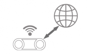 | BLUEBOX | Router for remote saw service. | OP |
 | 510-DPP | Automatic end stop of the upper position. | ST |
 | NPH | Hydraulic tension of band. | ST |
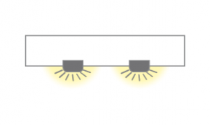 | LED | Lighting of workink space. | ST |
 | 510-VTT | Worm chip extractor for long chips (stainless-chips), includedd 1 pc of BOX-TRI. | ST |
 | HPV | Solution of moving guides of band together with jaws of the vice. | ST |
 | PEGAS ASR | ASR = Automatic cutting feed regulation based on set parameters. | ST |
 | RTS-A | Regulation press of vice – set of 2 pcs for bothvices. | ST |
 | ECK | Cleaning brush of blade driven actively by motor. | ST |
 | CMU-1 | Opening of cutting zone from feeder side. Without contact moving of blade to upper position. | ST |
 | OCP | Rebounding jaw of feeder vice. Controled by short-stroke cylinder, placed on linear leading. | ST |
 | 510-OCS | Rebounding jaw of stationary vice. Controls by short-stroke cylinder, placed on linear leading. | OP |
 | ATB | Automatic feed of the material precisely into the cutting zone. | OP |
 | 510-KKR | Check of cut perpendicularity. | OP |
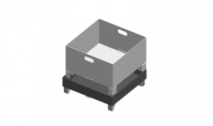
 | BOX-PCS | Box for cutted pieces with emulsion draining to the waterproof tank. | O |
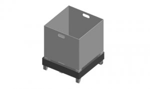
 | BOX-TRI | Box for the chips with emulsion draining to the waterproof tank. | O |
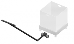 | BOX-TAH | Tool for manipulation with BOX-PCS and BOX-TRI. | O |
 | 500-HP-A | Hydraulical upper vice for mounted on the main vice and on the feeding vice. Hydraulic upper clamping tighten the material in vertical sense by the hydraulic cylinder. Set of 2 pcs. With this option is impossible use standard equipment 510-DPP! | O |
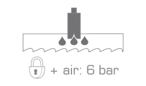 | MINI LUBE 54 | Wasteless lubricating system – 2 pumps, for blade 54 mm. Instead of emulsion cooling, specially for cutting profiles and non-ferrous metals, necessary supply of pressed air 6 Atm. | OP |
 | LASER LINE | Laser indicator of cut position. | OP |
| 510 - QPARTS | Set of easy worn away spare parts : | O | |
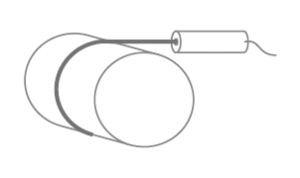
| 510-SET M42 | Set of 10 blades in M42 quality – with customer’s choice of teeth. 6060x54x1,6 | O | |
| 510-SET M51/10 | Set of 10 blades in M51 quality – with customer’s choice of teeth. 6060x54x1,6 | O | |
| 510-NAV | Manual instruction – printed version. | O | |
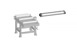
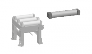
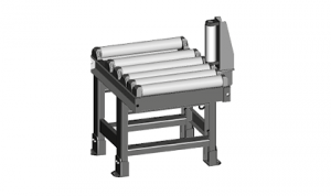 | 500-RDZ 1000/620 | Special output roller table, with a gutter which prevents leakage of emulsion on the floor. Lenght 1000 mm, width of cylinders 620 mm, 6 rollers, capacity 1700 kg/m. | O |
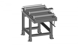 | RDT 1000/620 | Robust roller conveyor with coolant gutter. Length 1000 mm, width of cylinders 620 mm, 3 rollers, it is possible to put them for RDR or RDL, capacity 2500 kg/m. | O |
 | RDT 2000/620 | Robust roller conveyor with coolant gutter. Length 2000 mm, width of cylinders 620 mm, 5 rollers, it is possible to put them for RDR or RDL ,capacity 2500 kg/m. | O |
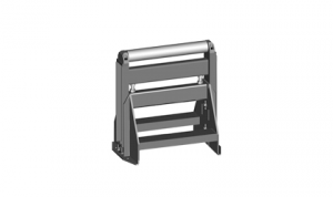
 | VZM-620 | The cylinder of rollertable, which is driven by electroengine, with 620 mm, is able to lift the material hydraulically above the level of other rollers. It is solution for later assembly to the standard rollertable RDT insta 2pcs of original cylinders. Control of the roller is independent on the controlling of the machine, the roller has its own controlling panel. | OP |
 | 500-RDH | Independent movable cylinder, adjustable height, capacity 1000kg. | O |
 | 500 V | Roller of roller table RDT put into gap. | O |
| 500-V-P | Cylinder (full material 620 mm length). Additional charge for nitriding of 1 cylinder. | O | |
 | 500-RBR | Side support fixed cylinder, height 280 mm, diameter 87 mm with its own frame, mounted to roller tables RDT. | O |
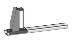 | 500-RBRS | Side adjustable roller, with its own steel frame, and with the movable leading 620 mm, fixed by 2 pcs of T-nuts. Height 280 mm, diameter 87 mm. | O |
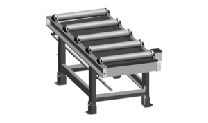
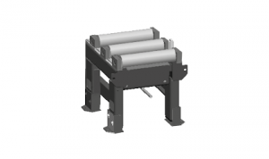 | 510-TDT 1000/570 | Input or output extra robust roller table. Lenght 1000 mm, width of cylinders 570 mm, 3 rollers. Bearing capacity 2000 kg/m. Cylinders with surfacing – hardness 55 HRc. | O |
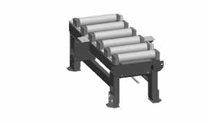 | 510-TDT 2000/570 | Input or output extra robust roller table. Lenght 2000 mm, width of cylinders 570 mm, 6 rollers. Bearing capacity 2000 kg/m. One vertical roller RBR is a piece of equipment of the roller conveyor. Cylinders with surfacing – hardness 55 HRc. | O |
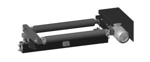
| 510-TDM 2000/570 | Input or output extra robust roller table with the drive. Driving by electrical engine, vorm gearbox and inverter. Lenght 2000 mm, width of cylinders 570 mm, 6 rollers. Bearing capacity 2000 kg/m. One vertical roller RBR is a piece of equipment of the roller conveyor. Cylinders with surfacing – hardness 55 HRc. | O | |
| 510-TDML 2000/570 | Extra robust lengthening 2 m segment with driven rollers, assembled to TDM 2000/1000. Lenght 2000 mm, width of cylinders 570 mm, 6 rollers. Bearing capacity 2000 kg/m. One vertical roller RBR is a piece of equipment of the roller conveyor. Cylinders with surfacing – hardness 55 HRc. | O | |
 | 510-TDT-RBR | Side fixed roller, height 650 mm with its own steel frame. | O |
 | 510-TDT-RBRS | Side adjustable roller, height 650 mm with its own steel frame, and with the movable leading, fixed by 2 pcs. of T-nuts. | O |
 | 510 V-TDT | Roller of roller table RDT pasted into gap. | O |
Tech. data NO241 are valid on 1.1.2024. Producer has the right to make changes of technical data.
Values contained on this page are only for information purposes. This information is not an offer and is not a public promise. This indicative offer does not give right to close a contract. The only guiding document for the contract is a valid price list.