Joint band saw machines ->
Semiautomatic band saw machine ->
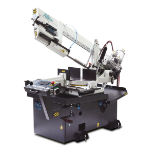
300x320 SHI-LR
 300x320 SHI-LR / Semiautomatic band saw machine

| mm | 0° | 45° | 60° | -45° | -60° |  |
 |
|---|---|---|---|---|---|---|---|
 |
300 | 300 | 200 | 270 | x | x | x |
 |
320x290 | 300x280 | 190x200 | 270x200 | x | 320x160 | 280x125 |
 |
 |
 |
 |
 |
|---|---|---|---|---|
| 3x400V | 2,4 | 20-100 | 3660x27x0,9 | 650 |
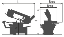
| Lmin | Lmax | Bmin | Bmax | Hmin | Hmax | V |
|---|---|---|---|---|---|---|
| 2050 | 2050 | 1170 | 1170 | 1420 | 2040 | 800 |
- Semiautomatic machine with hydraulic manipulation.
- The machine is designed for cutting of material in vertical and angle cuts, angle cuts are possible to set fluently from 60° right to 45° left.
- It is suitable for piece production and small series production.
- The machine is designed to saw steel materials, but also non-ferrous and light metals. However, we recommend consulting the manufacturer about this option.
Control system:
- The Controler with PLC MITSUBISHI and features an automatic feed control BRP.
- Control panel MITSUBISHI as standard equipment. It uses touch display and PLC, which enable semi-automatic cutting (basic setting encluded) as well as communication with operator.
- Controler show lot of information about cutting proces on the display:
- Cutting cycle indication,
- indication BRP,
- indication – blade tightening,
- time of the cut,
- loading of blade in amperes,
- speed of the blade,
- cutting times measuring,
- list of error messages.
- User´s setting:
- autostop of hydraulic unit
- mode of arm moving after end of the cut
- mode fadt moving of the arm
- mode time lag of shift speed
- mode blade moving
- mode jaw moving after cutting cycle finish
- diagnostic of inputs and outputs"
- STOP function – cutting: it enables to stop cutting by pressing STOP button at any time. The Frame goes up with the running blade without opening the vice.
- Regulation of shaft speed (moving to cut) is manual and uses throttle valve placed beside control panel. Automatic (safety) regulation of shift speed PEGAS BRP. Principle: Machine will stop after exceeding set loading (defined in ampers).
- The ergonomical control panel is mounted on the movable console. The control panel is equiped with mechanical buttons and digital display of the machine control system. Mechanical buttons controls basic saw movements (arm, vice) and cutting cycle start. The safety button is present on the panel aswell. Buttons for controlling the movements of the machine are part of a high-quality foil keyboard.
Construction:
- The machine is constructionaly designed in that way, so that it corresponds to extreme exertions in productive conditions.
- The arm of the machine is made of cust iron and it is designed to ensure the power and the precision of the cut. Arm is 25 grades sloped, it increases the lifetime of
- The arm rotated by a shaft (joint) which is support by adjustableconical bearings
- Drive pulley and tighten pulley are both metal castings.
- Upper working arm position controled by automatic stopper (DPP)
- The down working position of the arm controlled by the miscroswitch. In the end position microswitch is on, arm goes to selected upper position.
- The vice is made from cast iron. Jaws ensure safe clamping of the material.
- The hydraulically operating vice with short travel is placed in an adjustable dovetail groove.
- Moving jaw of the vice is manual with a wheel and trapeze thread. Speedy jaw adjustment is achieved by means of a lever, spring and trapeze half-nut.
- Basic part of the vice moves according to the direction of the angle cut setting, fixation is made by the handle.
- Turn table is cust iron. A turntable gives a big place for supportion of material and its perfect clamping.
- Manuall turning of the table for angle cuts, angle fixation using handle. The turning table has autoarresting every 15 grades ( the groove with the spring ).
- General angles are adjusted by the nonius. It is possible to equip the machine by reading of angle by incremental sensor and magnetic tape - indicated on the digital display on the control panel MITSUBISHI.
Basic equipment of machine:
- The blade leading in guides with hardmetal plates and leading bearings and along cast iron pulleys.
- There is a guide situated on the firm beam on the drive side. On the tightening side there is the guide situated on the moving beam.
- The guide beams of moving band guide is adjustable. Manual adjustment and fixing of the guide beams.
- The beam of the guide is moving in sliding leading.
- The saw-band is equipped with a guard, which protects the operator from millings and cutting emulsion.
- Mechanic tightening of the blade.
- Automatic indication of blade tension.
- A passive driven cleaning brush for perfect cleaning and function of blade.
- Drive of machine is solved by worm gear box with maintenanceless oil filling. Three-phases electromotor with double winding, with a frequency converter for a fluent regulation of the blade speed from 20 to 100 m/min. Sturdy flange with shaft. Termoprotection of engine.
- The cooling system distributes cutting emulsion to the band guides.
- Massive base with a tank for chips. Base is designed for manipulation manipulation with machine by pallet truck and also by any hight lift truck.
- Indication of blade tightening and opening of the cover.
- Controlling 24 V.
- Maschine is equipped with hydraulic system which controles all functions of that maschine. It pushes the arm to cut, pulls up the arm and opens and closes vices.
Basic accessories of machine:
- Band saw blade.
- Set of spanners for common service.
- Manual instructions in eletronic form (CD).
Operating cycle:
After manual adjustment of the jaws the operator starts the cycle with a switch on the control panel. The hydraulic cylinder of the vice grips the material and the saw starts working. The cutting speed of the arm is controlled by a throttle valve. Arm and vice movements after cut finish following set user parameter. The vice opens and the operator can handle the material.
Do you like this?
Contact us
or send inquiry!
or send inquiry!