Highly-efficient double-column band saw machines ->
Herkules ->
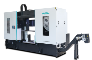
850x1000 HERKULES X
 850x1000 HERKULES X / Herkules
 It's no longer on sale
| mm | 0° | 45° | 60° | -45° | -60° |  |
 |
|---|---|---|---|---|---|---|---|
 |
850 | x | x | x | x | x | x |
 |
1000x850 | x | x | x | x | 1000x460 |
 |
 |
 |
 |
 |
|---|---|---|---|---|
| 3x400V | 11,0 | 15-80 | 9490x67(80)1,6 | 7800 |
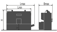
| Lmin | Lmax | Bmin | Bmax | Hmin | Hmax | V |
|---|---|---|---|---|---|---|
| 4460 | 6000 | 2000 | 2000 | 2820 | 3260 | 620 |
- Highly productive semi-automatic, hydraulically manipulated two column band saw machine.
- The machine is designed for vertical cuts.
- It is suitable for serial production in industrial premises. The machine is designed to saw steel materials, but also non-ferrous and light metals. However, we recommend consulting the manufacturer about this
- No other materials may be sawn without approval from the manufacturer.
Control system:
- Machine is equiped with programmable PLC SIEMENS SIMATIC S7-1200. Drive of band blade and movement of arm are completely controlled and drive by SIEMENS technology.
- The coloured touch screen HMI SIEMENS TP 700 COMFORT enables easy communication with an operator. It shows working conditions (blade speed, moving to the cut, cutting parameters etc.)
- SEMIAUTOMATIC CYCLE: The machine cuts the material immediatelly in a semiautomatic mode.
- Regulation of cutting feed is realized by controlled system by the servo-motor and throttle valve of hydraulic. Then is reached very precise cutting feed. Operator will input into program requiered cutting feed (mm/min) and bandsaw this cutting feed precisely set.
- Two basic regimes of automatic system regulation (ASR): ARP a RZP.
- RZP = Zone regulation. System enable to cut material in 5 zones, because of setting optional cutting feed and blade speed according on blade position.
- ARP = System of the automatic regulation of the cutting feed rate depending on the cutting resistance of the material or blunting the blade. Systém offers two basic modes of ARP: BIMETAL and CARBIDE.
- BIMETAL mode is suitable for optimalization of the cutting feed when cutting profiles by bimetal blades. The cutting feed is higher if the blade cuts sides of the profile. As the blade reaches the full material, the system reduces the cutting feed automatically so that teeth gap of the blade would not be filled.
- CARBIDE mode is suitable for cutting of full bars. If the blade is old (blunt), loaded is the cutting feed reduced Reaction time is slower than in mode BIMETAL.
- The control panel is placed in the tightening pulley cover. The control panel is equiped with mechanical buttons and digital display of the machine control system. Mechanical buttons controls basic saw movements (arm, vice) and cutting cycle start. The safety button is present on the panel aswell. Buttons for controlling the movements of the machine are part of a high-quality foil keyboard.
- Safety module with autodiagnostics.
Construction:
- The machine is constructionaly designed in that way, so that it corresponds to extreme exertions in productive conditions. Massive construction enables using of carbid blades comfortably.
- The arm of machine with columns situated as near the clamping vice as possible minimizes vibrations and enables max. cutting performance.
- The arm of the machine is robust, heavy weldment and it is designed so that a toughtness and a precision of cut was ensured.
- The arm moves along two columns using a four row linear leading with a high loading capacity. Arm movement using two hydraulic cylinders.
- The robust steel pulleys sloped of 25 degrees regarding the level of the cut. Thanks to sloped arm the twist of the blade is eliminated and these is possibility to bring the blade closer to the minimal distance from the linear leading on columns. This arrangement eliminates vibrations and enables the max. cutting performance of the machine.
- The arm uses incremental sensor for evaluation of current position above material. Upper working position of the arm is possible to set in control system.
- Down working position is set with adjustable mechanical stop and microswitch. Down working position of the arm is also possible to set in the saw control system. After reaching bottom working position the arm stops in the position set in the system.
- Vice is robust steel weldments.
- Main vice with divided jaw that clamps the material in front of as well as behind the cut. The jaws allow a safe grip.The optimalization of the chip movement through the fixed jaw directly to the chip extractor.
- Jaws of the main vice move on two rails of linear leading using hydraulic cylinder. One jaw is longstroke (the movement by longstroke hydraulic cylinder), one is fixed.
- Regulation valves for setting a vice pressure in hydraulic system.
- The blade leading in guides with hardmetal plates and leading bearings and along cast iron pulleys.
- Maschine is equipped with hydraulic system which controles all functions of that maschine. It pushes the arm to cut, pulls up the arm and opens and closes vices.
- Blade leading though the guides solved by “clearanceless blade leading” – blade is push to guide by hydraulic clinder, which enables comfortable blade exchange
- There is a guide situated on the firm beam on the drive side. On the tightening side there is the guide situated on the moving beam.
- The guide beams of the blade are adjustable in the whole working range. A giude moving is connected with a vice-jaw movement so that to achieve the minimum distance of the guide and material. That is why it is not neccessary to set the position manually.
- Hydraulic tightening of band.
- Automatic indication of blade tension.
- A cleaning brush is driven by an electroengine and ensures perfect cleaning of a blade.
- There is a planet gear box drive and a three-phase electroengine, a fluent regulation of a blade speed by a frequency converter for a fluent change of blade speed.
- The cooling system for emulsion, leaded to the guides of the blade and by LocLine system directly to the cut groove.
- Massive base with a tank for chips and with chip extractors. Base is designed for manipulation manipulation with machine by crane.
- Indication of blade tightening and opening of the cover.
- Controlling 24 V.
Basic equipment of machine:
- Chip extractor
- Lighting of workink space.
- Band saw blade.
- Set of spanners for common service.
- Manual instructions in eletronic form (CD).